3D Photos
3D Photos use depth to make 2D images more compelling by adding a parallax effect. By allowing the viewer to see the 2D image from different angles in 3D space, 3D Photos can replicate how humans perceive nearer objects to move more than distant ones when our viewpoint changes. Think of how when looking outside a window, objects in the distance barely move compared to those in the room as you move around. Although depending on how much information is used to construct the photo, the viewing range can be quite narrow, so they are actually somewhere in the middle between a traditional 2D and 3D experience.
Hover your mouse over the image, or tap into it to open the post on Facebook.
3D Photo on Facebook created by Asur Illustrations.
3D Photos can be incredibly powerful, especially when viewed in virtual reality. While support for VR is limited, Facebook allow users to view 3D Photos in VR from the native Quest web browser. The ability to see images in 3D can bring them to life, making them feel like they're right in front of you. For example, people have used this technology to create 3D photos of loved ones who have passed away, allowing them to feel like they're still with them (source). It's heartwarming to see how this technology can bring people closer together, even in difficult times.
About the project
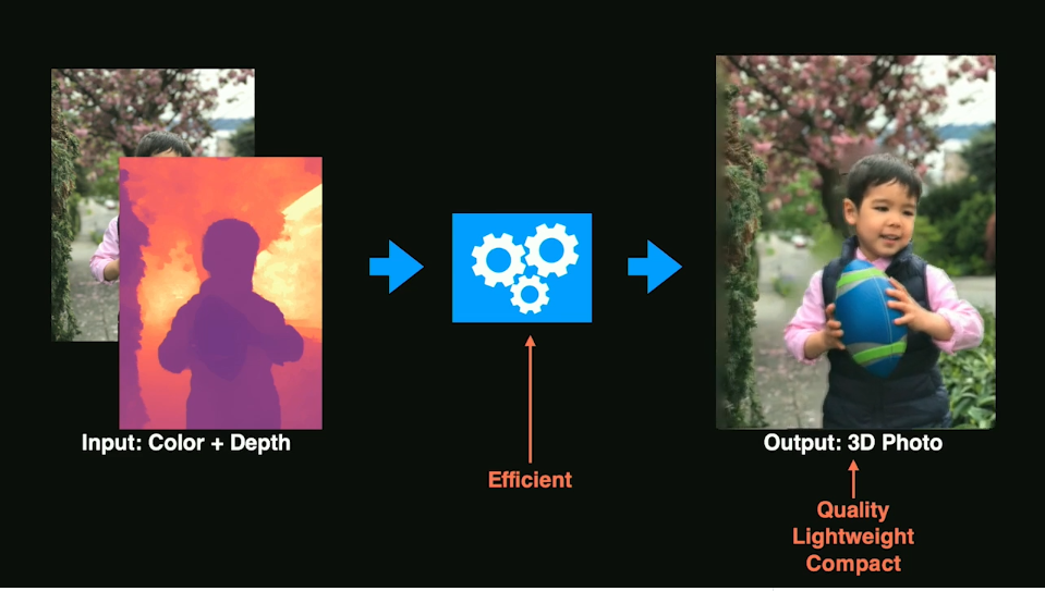
My team at Facebook, Computational Photography, developed a method to generate 3D photos easily using "portrait mode" photos taken on iOS and upload them directly to Facebook. I helped launch the experience back in 2018 (here's a TechCrunch article covering the initial launch). Post-launch, I worked with several Android OEMs (e.g. Samsung) to add the ability to create 3D photos using their Android devices. Most recently, we integrated 3D Photos into Rayban Stories which can capture depth with its dual-cameras.
The most unexpected result we saw from launching 3D Photos was from people using a 3rd party app to hack iPhone's Portrait Mode photo format and make 3D Photos with their own custom depth maps, many of which produced really amazing results! Recognizing the need to support power-users, I built support to create 3D photos using their own depth images on the browser.
Our motivation for the project was to democratize the creation of 3D content. We wanted to give anyone who can take a good photo the ability to create 3D content without advanced knowledge of 3D modeling, or complex and expensive 3D reconstruction systems. Eventually, we achieved this goal with an AI algorithm that is able to approximate the depth of any photo and now anyone can create a 3D photo from any regular photo on their modern smartphone. In 2020, we published a paper about our method to SIGGRAPH called One Shot 3D Photography
How It Works
If you're curious about how it all works, here is a brief presentation on how 3D Photos work at Facebook that I gave at the LDV Vision Summit back in 2019. For more details, in this section I walk through how someone might make their own 3D Photo using a simpler algorithm and more manual steps. Complete code and Unity project files linked at the end.
Francis Ge - 3D Photography from LDV Capital on Vimeo.
At a very high level, we turn the 2D image into a mesh in 3D space using perspective projection. Different parts of the image appear to move at differing speeds creating parallax. The image is also separated into different layers so that when the camera moves, the viewer can also see behind the front layers. The underlying principle is pretty simple, but there a lot of challenges to creating a compelling result.
Rendering of a 3D Photo mesh in Unity
Obtaining a depth map. Depth refers to the distance to the camera, and a depth map (or image) records how far each pixel is from the camera. There are many ways to obtain depth information like stereoscopy, or LIDAR captures. If you have access to the 3D scene itself in a game engine, the precise scene depth can be read from the GPU and saved to disk. These days, it has become common for phones to record to depth information which is used for image effects like depth of field. For photos taken on iOS in "Portrait" mode, this depth information is stored inside the photo and can be extracted. Using exiftool, you can see inside the metadata for a photo and extract the embedded depth map:
$ exiftool IMG_7876.jpg
...
MP Image 2                      : (Binary data 38421 bytes, use -b option to extract)
MP Image 3                      : (Binary data 75418 bytes, use -b option to extract)
MP Image 4                      : (Binary data 670630 bytes, use -b option to extract)
MP Image 5                      : (Binary data 83872 bytes, use -b option to extract)
MP Image 6                      : (Binary data 51057 bytes, use -b option to extract)
MP Image 7                      : (Binary data 38111 bytes, use -b option to extract)
MP Image 8                      : (Binary data 40418 bytes, use -b option to extract)
...
$ exiftool -b -MPImage3 IMG_7876.jpg > disparity.jpg
You may notice there are a bunch of other images stored as well depending on which phone the image was taken with, so you may need to just extract all of them and see which one looks like the depth map. Something to note is that typically the "depth" stored in these images is actually stored as disparity. The important thing to remember is that disparity is inversely proptional to depth, so a conversion needs to be done. See this page for more details on disparity vs depth.
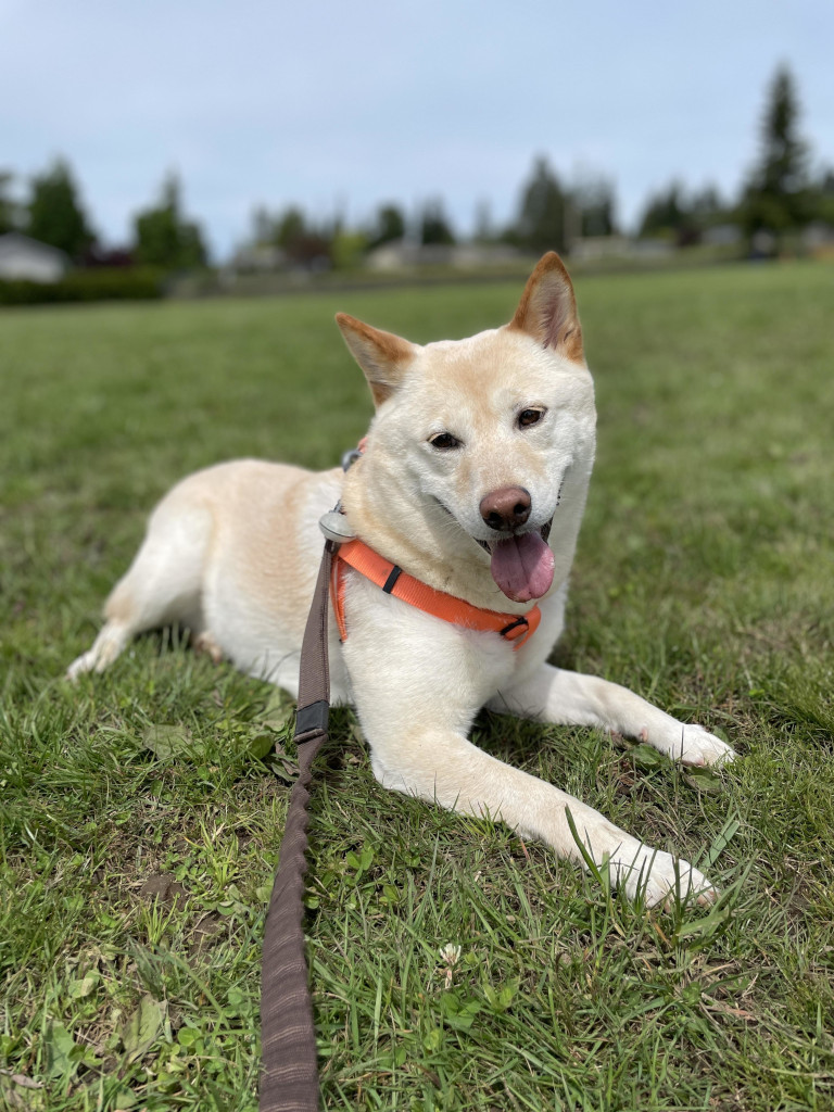
Portrait photo
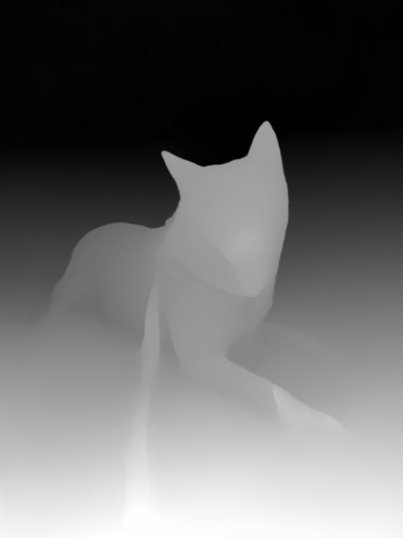
Depth map (stored as disparity)
Bringing it into 3D. The first step is to create a flat quad mesh with a bunch of subdivisions that we can texture with the photo. The exact amount of vertices doesn't matter too much, however the more triangles there are the more detail that can be captured so two triangles per pixel in the depth map is a good rule of thumb. If we look at the mesh with a perspective camera, you may notice things may look a little off, or warped. This is because putting the photo onto a flat mesh is doing an orthographic projection. Each vertex is a different distance to the camera. In order to render correctly from the POV of the perpsective camera, we need to warp the mesh such that each vertex is equidistant to the camera.
To assign each vertex an XYZ position, we'll first need the field of view of the camera that took the photo. In other words, how many degrees vertically and horizontally is shown by the photo. Unfortunately, it's not very straightforward to get this information. If lucky, this information might be found in the EXIF data for the photo. Otherwise, the information might be provided by the manufacturer of the camera / sensor and can be found online.
$ exiftool -fov IMG_2244.jpg
Field Of View                   : 69.4 deg
If there's only one value (instead of two for horizontal and vertical FOVs), then that likely refers to the diagonal FOV. Diagram below shows the relationship between them and how to convert from diagonal to horizontal/vertical FOV given the width and height of the image.
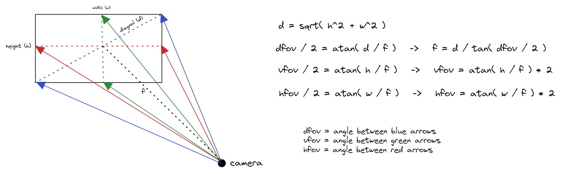
Once we have this, we can assign each vertex an XY angle, and then project from the camera origin in that angular direction.
// Compute UV coordinates for the vertex given its 2D planar coordinate <col, row>
Vector2 uv = new Vector2(
  col / (float)(width), // Range [0, 1]
  row / (float)(height) // Range [0, 1]
);
// Compute a horizontal and vertical angle for the vertex
Vector2 angles = new Vector2(
  degToRad((uv.x - 0.5f) * cameraHorizontalFov), // Range [-cameraHorizontalFov / 2, cameraHorizontalFov / 2]
  degToRad((uv.y - 0.5f) * cameraVerticalFov) // Range [-cameraVerticalFov / 2, cameraVerticalFov / 2]
);
// Convert angles to a vector from the origin
Vector3 viewingDirection = new Vector3(
  (float)Math.Sin(angles.x),
  (float)Math.Sin(angles.y),
  (float)Math.Cos(angles.x)
).normalized; // Normalize the direction
// Project from the virtual camera position outwards in direction of vector
float distance = 1.0f; // All vertices are equidistant from the camera
Vector3 vertex = viewingDirection * distance;
Adding depth. In the previous calculation, each vertex was equidistant from the camera origin. To add depth to the scene, each vertex will instead sample the depth map and use that value for the distance to the camera.
// Sample depth map stored as disparity.
// SampleTexture function: https://gist.github.com/kumorikuma/9ce8bb17df5dee677ec8c2f8ce1530ab
float disparityDepth = SampleTexture(uv, depthPixels, depthImage.width, depthImage.height).r;
// Convert disparity to depth as "distance from camera"
// The reason we divide by disparity + 1 is that when disparityDepth = 0, we don't get infinity (NaN).
// It essentially "caps" the range to maximum of 1.
float depth = 1 / (disparityDepth + 1); // Range [0.5, 1]
// Normalize the depth
depth = (depth - 0.5f) / (maxDepth - 0.5f); // Range [0.0, 1.0]
// Brings the value from the range [0.0, 1.0] to [1.0, kMaxDistance + 1].
// We don't want any vertices to sit at 0 because then they're at all a singular point.
// We may want the mesh to actually extend farther which will produce different artistic effect.
float kMaxDistance = 1.0f;
float distance = depth * kMaxDistance + 1;

// Project from the virtual camera position outwards in direction of vector
Vector3 vertex = viewingDirection * distance;
Notice how from the camera perspective, the scene doesn't change at all because only the vertex distance to the camera changes, which is imperceptible when the camera is placed at the center from which the vertices are projected out from. (Note that you will see a difference if the camera is moved closed to the mesh.)
For an animation like a dolly-zoom, this already works quite wonderfully! If the effect is too subtle, we can crank up the kMaxDistance value in the above calculation to increase the difference between the foreground and background.
Left (no depth), Middle (kMaxDistance=1), Right (kMaxDistance=10)
However, if we look behind any foreground objects, we see a lot of striping artifacts. This is because we have triangles that are connected from the background and stretched all the way to the foreground. One way we can fix this is to disconnect the background and remove these triangles.
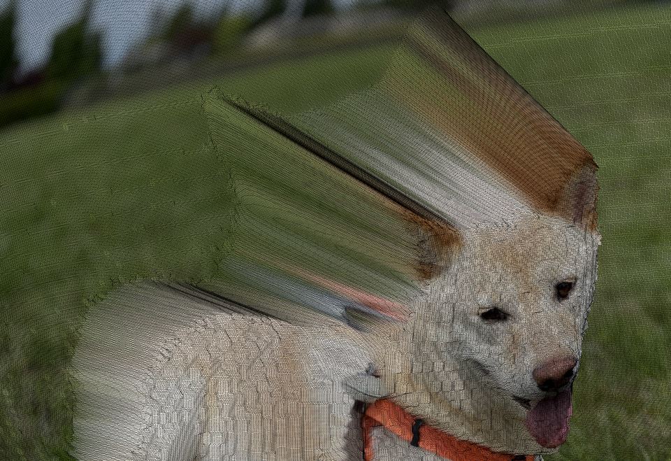
Separating the foreground from the background. Identifying which parts of the image are foreground vs background (aka foreground/background segmentation) is a very complex problem, and there are many different ways to approach this. Since we have the depth information, a simple approach could be to make the assumption that the foreground and background have very different depths, so a dramatic shift in depth means that there's a transition between foreground and background. When drawing the triangles, we could examine each vertex, and if the depth is past a certain threshold, avoid drawing the triangle.
A more accurate way might be to use AI models such as Removal.ai to handle this problem. Removal.ai limits the resolution for free users, but since we're just using it as a mask, it doesn't need to be full resolution. On iOS, you can tap and hold the subject of a photo to lift it away from the background. I found that iOS is more accurate, but the separated foreground is cropped and needs to be re-aligned with the background.
Original Photo
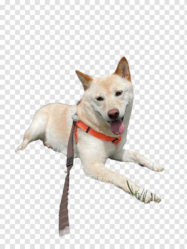
Foreground Image (Removal.ai)
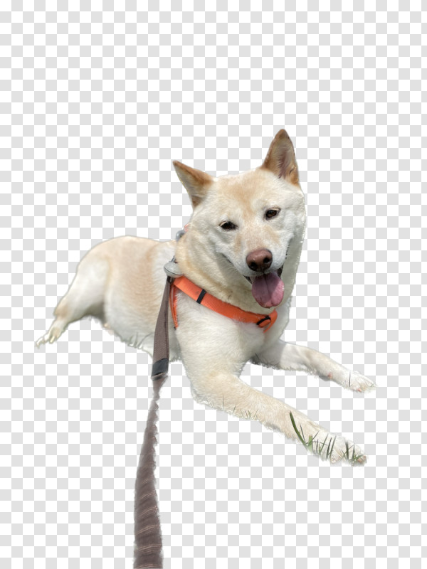
Foreground Image (iOS)
With the foreground image, we can now classify vertices as being part of the background or foreground depending on their alpha value. Some areas are partially transparent, so we will just say if alpha > 0, then it is part of the foreground. When creating triangles in the mesh, we can do a simple check to make sure that the triangle should only be created if all of its vertices are in the foreground, or if all of its vertices are in the background. Unfortunately... it only kind of fixes the problem.
The reason this is happening is because there's not a clean binary separation between the foreground and background usually. If we zoom in on the depth map, we can see there are grey in-between values on the border. Even if we pre-processed the depth map to have clean-cut edges, we are pretty much guaranteed to have errors. This is why in the foreground image, the borders have some alpha value in-between 0 and 1 instead of being binary.
Depth map (stored as disparity)
Magnified region
Filtering the mesh. One way to address this is by doing some post-processing on the mesh. Specifically, a median filter to remove outliers, followed by an averaging filter to smoothing out the mesh. Since our vertices are arranged in a regular grid, we can treat them the same way as we'd go about filtering a regular image. A couple of important things to note... Instead of filtering the raw positions of the vertices, I opted to filter just the distance to camera, then afterwards re-projecting the vertex with the new distance in order to preserve the horizontal/vertical angular position of the vertex (or else the shape of objects will distort). It's also important to not mix background and foreground vertices and blurring across them.
Sealing the gaps in the background. Now that the stripes are gone though, we're left with a hole in the background! It won't be seen if we only move the camera forward/backward. However if the camera is moved to the side at all, we're going to be rendering the skybox or clear color.
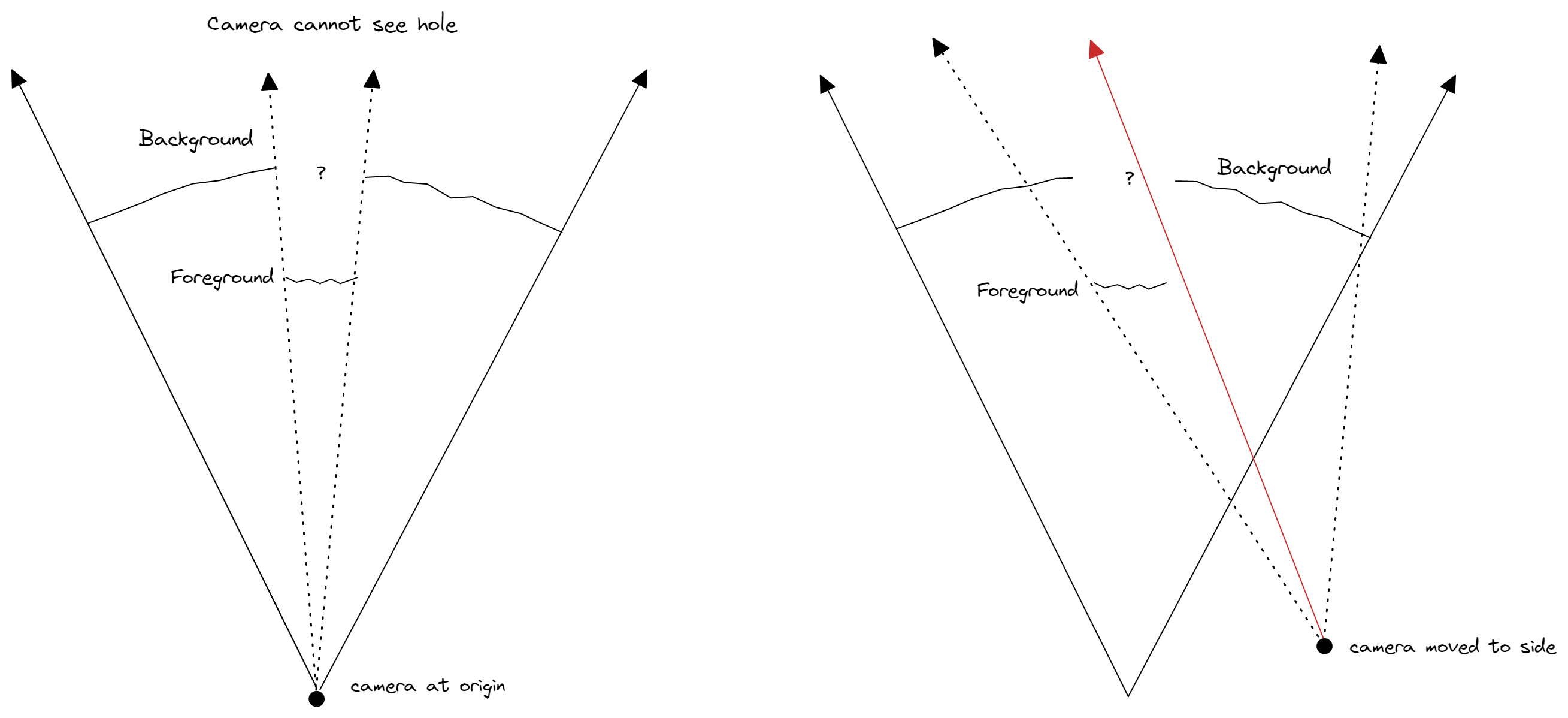
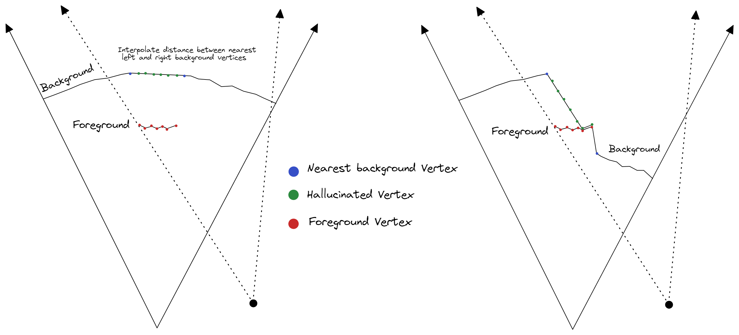
To fill this gap, a simple approach is for each vertex that is in the foreground, generate a new vertex (we'll call it a hallucinated vertex), and push it into the background using an interpolation of nearby background vertex distances as an estimate. There might be a situation where the estimated distance is actually greater than the foreground vertex distance, and in this case it could simply just be pushed back behind the foreground vertex (as seen in diagram below on the right).
Lastly, the newly hallucinated vertices cannot use the same texture as the foreground anymore or it will show the foreground in the background. They need to be separated into two separate meshes so they can use different textures. We can simply cutout the foreground from the background, but then we'll need to fill in that area with something...
Inpainting the background. This step is also very complicated, however fortunately there are many AI algorithms these days that can fill in the missing part of the background (also known as inpainting or content aware fill), such as OpenAI's Dall-E which is free to try. Dall-E does an amazing job but it has a few quirks: the image must be 1024x1024, there needs to be a text prompt to describe the image, and it will slightly alter parts of the original image.
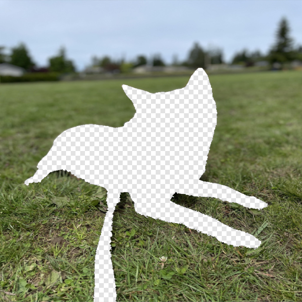
Background with foreground removed
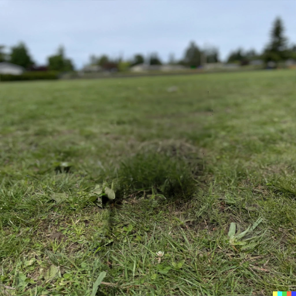
Background inpainted with Dall-E
It may require generating a few variations and messing with the prompt, but the result can be really convincing!
With and without background inpainting
Mesh Simplification. Earlier I mentioned that we'd want two triangles per pixel in the depth map in our quad mesh to capture all of the detail. In a 576x768 depth map, this results in a foreground mesh with 520,836 triangles, and a background mesh with 2,652,208 triangles. Way too large to be actually usable outside of a rendering! This can be optimized by assigning more triangles to areas with more detail. Large regions without much change (e.g. a flat surface) don't need as many triangles (as opposed to a curved surface for instance).
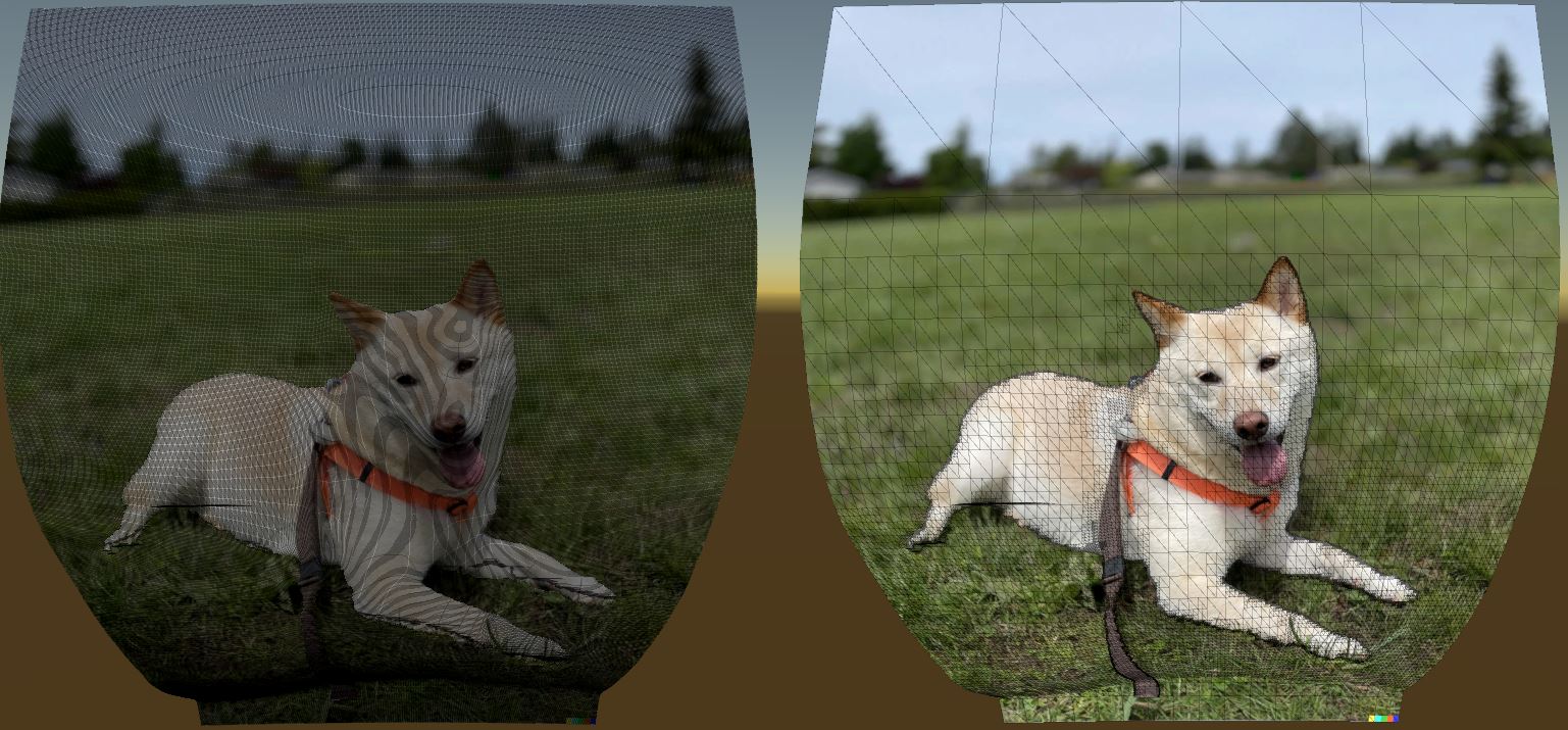
Before and after mesh simplification (3,173,044 tris -> 103,335 tris)
If done properly, there should little to no noticeable difference in the quality of the rendering.
Before and after mesh simplification (3,173,044 tris -> 103,335 tris)
There are many ways to tackle this. The edge collapse algorithm works on any triangle mesh by computing an error metric for each edge and iteratively merge the two vertices of the edge with the smallest error. Another approach is using quad collapse which iteratively merges two edges of a quad with the smallest error to form one edge. Since the triangles and vertices from the mesh generation step are arranged conveniently in a regular grid, I came up with a custom mesh simplification algorithm that recursively transforms flat regions of the mesh into simpler quads. In this case detail refers to amount of change in depth.
The algorithm works as follows... Take a rectangular region (start with the entire image) and compute the maximum deviation in distance (i.e. max - min) inside that region. If the deviation is below the specified threshold, simplify the region by creating a new vertex at each corner and replacing that entire region with two triangles. Otherwise, we will split the region into four quadrants, and then recursively repeat this check on each of those four rectangular regions. If the region becomes smaller than a certain size, then it could not be simplified and we keep all of the old vertices and triangles.
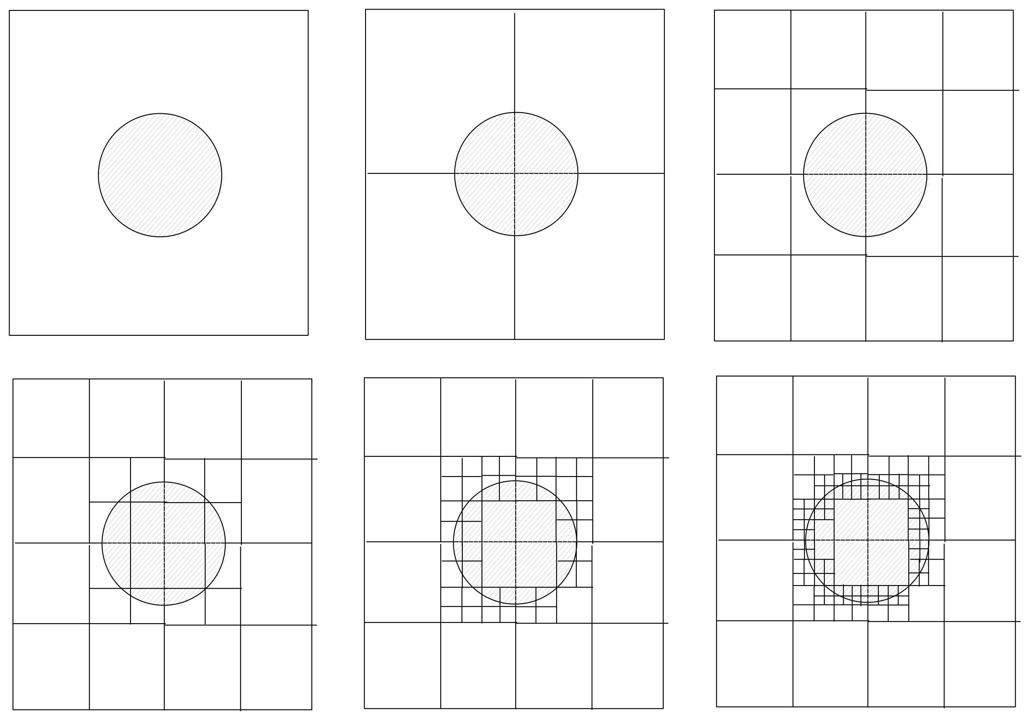
Illustration of recursively simplifying in 2D
This algorithm is quite fast since it can leverage dynamic programming. The distances for each vertex can be calculated in advance, and the min/max bounds for each region can be cached. There's one problem with this method, which is that it can create gaps because the lower resolution regions' edges are put against higher resolution regions' edges. It can be fixed by iterating through all the regions in order of descending size (i.e. low res first), and for all of the vertices that fall on the region's edges, move them such that they lie on the edge (which is simply a linear interpolation of the two vertices that form the edge). Additionally, each vertex should only be moved at most one time (from a higher resolution edge to a lower resolution edge).
Timelapse of simplification algorithm running
Removing jagged edges. Upon closer examination, one might notice the edges are jagged. This is exaggerated even more when using a lower number of triangles. This is an artifact of the algorithm running on a grid. A simple way to take care of this is to average the foreground edge vertices by their actual XYZ 3D positions instead of just the distance to the camera, which will move them away from the grid and give a more organic appearance.
Note: Mesh resolution is reduced to emphasize jagged edges
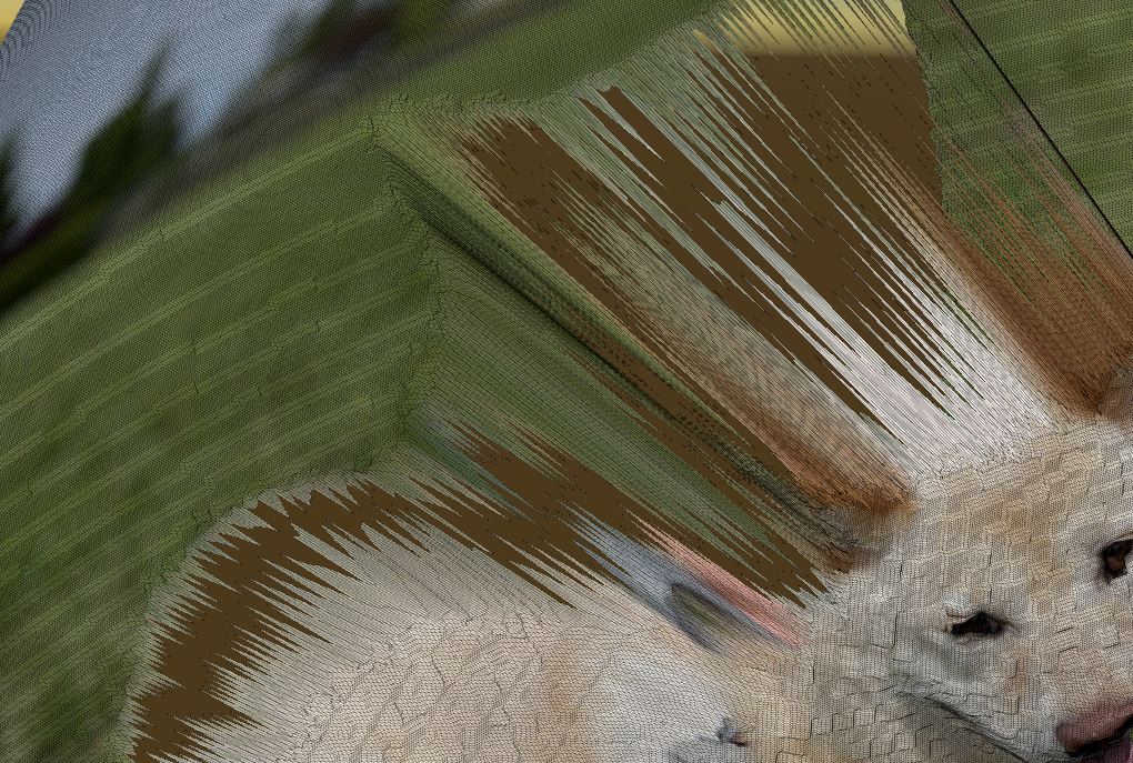
Feathering edges. One last thing to address is how there's not really a clear boundary most of the time between background and foreground. If we look closely at the paws on the dog for instance, you'll notice that there's leaves and part of the ground that get marked as being part of the foreground. Fur and hair also tend to create a 'fuzzy area' between the foreground and background. Some foreground detection algorithms attempt to handle this by feathering the edges or uncertain areas to be semi-transparent (i.e. opacity between 0 and 1).
This is exascerbated by how Dall-E modifies the original image slightly in the inpainting process. We can make this look slightly better by adding this feathering to our foreground mesh through a simple custom shader that takes in the foreground image and uses the alpha from that instead of just an alpha of 1. If there's no feathering in the foreground image, we can feather the mesh manually by precomputing the distance from each pixel to the edge of the foreground (i.e. making a signed distance field), and using that as a mask to adjust the opacity as the pixel.
The effect is most notable with this image on the paws and leash
And... that's pretty much it! There's definitely more that could be done with this (such as using Dall-E's outpainting as extending the FOV outwards), but I'll leave that as an exercise for the reader. Complete code and Unity project can be found here.
Looking Forward
The idea of letting people see an image from new viewpoints (known as novel view synthesis) has been around for a while. There is also a technique called light field photography that captures an image volume instead of a flat plane. Perhaps in comparison to other techniques, the principle behind 3D Photos is rather simple and limiting, but such simplicity lets us run the algorithm fairly quickly on most mobile devices and render the output (which is just a mesh and a texture) in any 3D viewer.
A promising new technique is known as Neural Radiance Fields, which uses deep neural networks to generate novel views without a 3D mesh representation. Read more about it here.
Video from Matthew Tancik's paper, Representing Scenes as Neural Radiance Fields for View Synthesis
Examples
If you're interested in seeing more 3D Photos, I recommend checking out Facebook 3D Photos and 3D Photos on Facebook. Asur Illustrations also has a lot of really amazing ones on their profile.
Leave a comment