360 Photos (Panoramas)
Panoramas are images that capture a wide-angle view, typically much more than the human eye can perceive at once. They can even capture an entire 360 degree field of view, both vertically and horizontally (360 photo). Phones are capable of taking panoramas by stiching together many photos using software, but typically for 360 photos, special cameras are used. Below is an example of a 360 Photo on Facebook taken by, Olēka.
Click and drag on the image to look around, or tap into it to open the post on Facebook.
Building a 360 Photo Viewer
For panoramas that just have a wider than normal field of view (such as those taken on mobile phones in "Pano" mode), simply displaying the wide image might be sufficient. However, since humans have a pretty narrow field of view, it becomes less natural to view the entire image at once as the field of view becomes greater. A special viewer is needed in order to display them in a way that is natural to consume. Since viewing panoramas with less than 360 degree field of view is a subset of a full 360 photo viewer, we will first talk about building a 360 photo viewer, then handle the case of small fields of view.
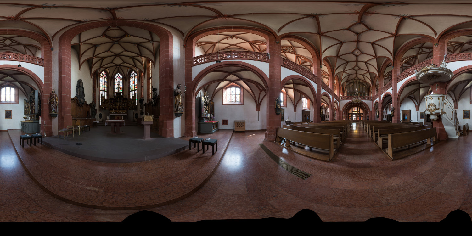
Example of a full 360 degree photo stored as an equirectangular projection. More on projections here.
360 Photo Formats
Imagine a floating, shiny metal sphere. All the light from all directions hit the sphere and reflect off of it. If you looked at its surface, it captures a reflection of its environment. This is essentially a 360 photo!
However, it needs to be stored in an easy to use format first. Maybe if we could 'unwrap' this sphere and spread it out into a rectangular shape, then we could store it just like a regular photo... it just so happens that people have been doing this since hundreds of years ago for an entirely different reason, and you have seen it many times before!
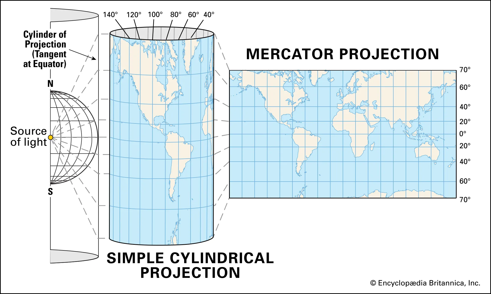
One way to do this is to wrap a rectangular image like a cylinder around the sphere. To generate this image, we would loop over all the pixels and map them to longitude (angle from the central meridian [-180º, +180º]) and lattitude (angle from the equator [-90º, +90º]) values on the sphere to obtain the color. Rather than referring to the XY pixel coordinates of the image, we'll refer to coordinates on the image with normalized UV texture coordinates so that it doesn't matter what the dimensions of the image are.
For the horizontal axis, the circumference of the sphere is equivalent to the circumference of the circumscribed cylinder. If you unfolded the cylinder into a rectangle, the width of the rectangle is equivalent to the circumference. This means that we can simply map the range for U [0, 1] linearly to the range for longitude [-180º, 180º]: longitude = U * 360º - 180º. For the vertical axis, half of the circumference of the sphere is equivalent to the height of the cylinder (for panoramas that have a vertical field of view of 180º, otherwise it will be less than half the circumference). If you unfolded the cylinder into a rectangle, the height of the rectangle is equivalent to half of the circumference. This means that we can simply map the range for V [0, 1] linearly to the range for lattitude [-90º, 90º]: lattitude = V * 180º - 90º. This is known as an equirectangular cylindrical projection, and many other types of projections exist that yield different properties.
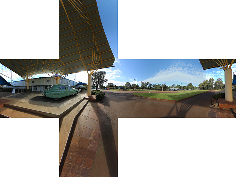
Another way to do this is to imagine placing a cube around the sphere. Then, we will project the sphere onto the faces of the cube instead of a cylinder. The faces of the cube can all be stored in a single image, or in separate images. This is known as cubemapping, and the resulting image is referred to as a cubemap.
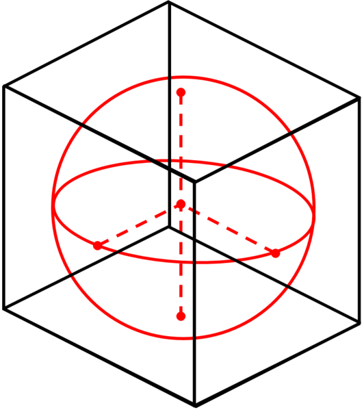
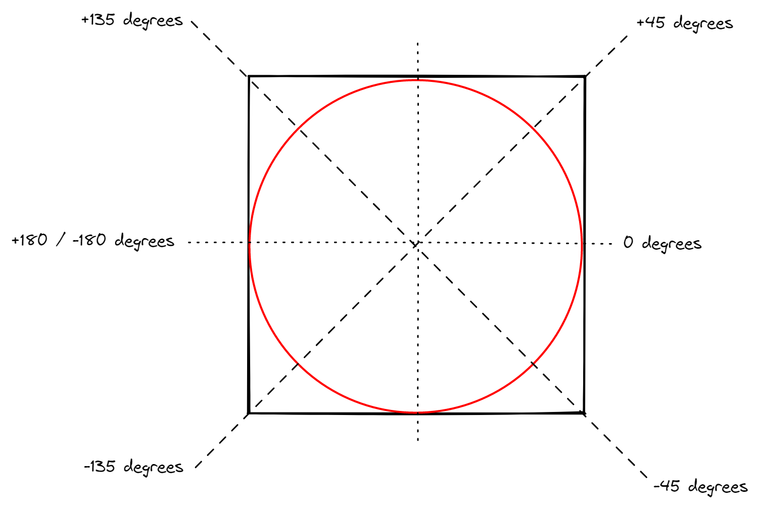
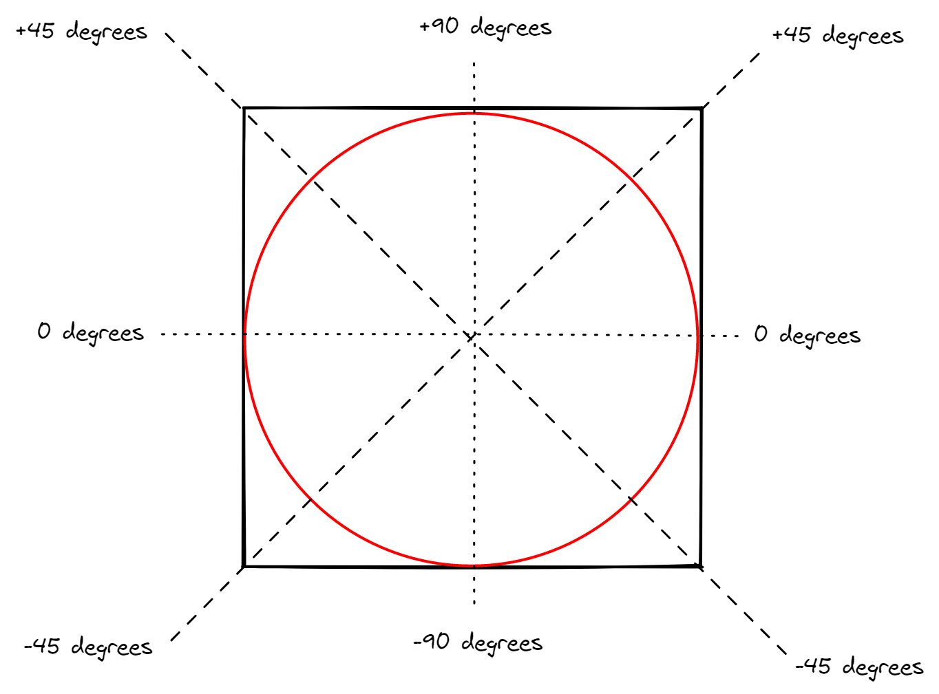
Each axis of each face of the cube will map to 1/4 of the circumference of the sphere, or 90º. If using separate images for each face, then we can use a straightforward linear mapping of the UV again. If using a single image for the cubemap, then it will be a matter of assigning to each face the proper UV range instead of using [0, 1]. Let's take a look at the horizontal axis first... The right face will have the mapping of U [0, 1] to longitude [-45º, +45º]. The left face will have the mapping of U [0, 1] to longitude [-135º, +135º]. And so forth. The vertical axis will be similar... but lattitude refers to the angle from the equator so things are a little different. Notice that care will need to be taken with the top and bottom faces. V [0, 0.5] map to lattitude [+/-45º, +/-90º], but V [0.5, 1] also maps to lattitude [+/-90º, +/-45º]. However, despite having the same lattitude values for two different values of V, the location of the sphere's surface is different because of the longitude.
.jpg)
Simple 360 Photo Viewer
Building a viewer for full 360 photos is fairly straightforward. Conceptually, we need to draw our 360 photo image onto a sphere (if using a cylindrical projection), or cube (if using a cubemap) by inverting the projection. Then we put a camera in the middle of the sphere or cube and rotate it! Concretely, this means that for each pixel we render, we need to compute the UV texture coordinates from the location on the surface of the sphere that the pixel represents. An easy way to do this is to write a custom shader for the geometry we're projecting the image onto.
As an example, I'll go over how to do this in Unity for an equirectangular projection. I don't rely on any Unity specific features though, so it should be easy to port to any 3d renderer. Full Unity project is available here.
First, add a smooth shaded sphere to the scene, and make sure that it's doublesided (or disable backface culling). Here is a doublesided sphere model that you can use. Technically we don't need the frontface, but I think it's nice to not have an invisible sphere floating in space unless you're inside it :p
Next, create a custom shader and material for the sphere. This shader will handle the mapping from the object space position of the pixels in 3D space, to UV coordinates on the 360 photo that we will sample with. For those unfamiliar with writing shaders in Unity, here's a basic tutorial about custom shader fundamentals.
The below shader is mostly Unity boilerplate for rendering a texture with a shader. Importantly though, it passes the object space (i.e. local space) location of the vertex through to the pixel shader.
In the fragment shader, we will first compute the longitude and lattitude from the position of the pixel on the sphere in object space. It's important to use atan2, which leverages both the x and y values to recover the longitudinal angle so that we can tell the difference when x is negative vs positive. Then we need to reverse the linear mapping as described previously, and convert the angles to the range [0, 1] to use as our UV coordinates.
And... that's pretty much it! If we want to add support for rendering panoramas in general, then we need to know what the vertical and horizontal field of view is for the panorama. We'll add these as properties to the shader so that they can be set in the material. I like to use degrees for user-exposed parameters since they are more user friendly, but that means we'll need to convert them to radians later in the shader.
The first change is to have separate behavior if the longitude or latitude value goes out of bounds. Here we just return a solid color, since likely there is some UX logic that prevents users from seeing out of bounds values anyway. We could also get fancier and have this return a blurred background instead, by generating a blurry low-res full 360 photo from the partial panorama and passing the shader two textures.
The next change is to how the longitude and lattitude map to the UV range. Since we want to render the entire photo, the UV range of [0, 1] we're sampling from stays unchanged. But instead of using the entire longitude/lattitude range, we now only use part of it. Continuing the explanation from earlier with the cylinder and sphere: the circumference of the cylinder isn't equivalent to the circumference of the sphere anymore, it now is some partial % of it, depending on the field of view. If the horizontal field of view is 180º for instance, then it's equivalent to half the circumference.
Unfortunately, there's no easy way to determine the field of view of a photo this just by looking at the image itself. With full 360 photos, we always know that the vertical FOV is 180º, and the horizontal FOV is 360º just by definition. With photos taken by speciality panorama cameras, this information is typically given by the manufacturer. Sometimes this data is stored in the EXIF data and you can find it by using a program to parse it like exiftool. There are also certain hacks you could do to try to estimate the FOV, but worst case, you could also just guess and check until the photo looks about right and not too deformed.
As for the UX logic of moving the camera around, I won't go into depth into that here since it's not too interesting. Basically, you just rotate the camera around the center of the sphere based on some input. You can also zoom into the image by moving the camera closer.
Optimized 360 Viewer
A big concern when it comes to 360 photos is filesize and bandwidth, potentially memory usage. 360 Photos can get really, REALLY big. Just looking around some websites, the typical photo is around 8000-15000 pixels in width. Since it's common to zoom into these photos, the higher the resolution the better! This causes: long loading times, excess bandwidth consumption, higher memory pressure... all of which are made exponentially worse in bandwidth restricted environments or lower end mobile devices.
The key optimization is that at any one point in time, the user is looking at some small portion of the photo. If we can chunk up the 360 photo into tiles, we can load tiles only when necessary, and unload them if needed. We can even create 360 photo LODs (level of detail), serving lower resolution tiles initially until the user zooms in, or the higher resolution tiles finish downloading. If you ever see blurry tiles on Google Street View for instance, that is what it is doing.
This is much easier to do using cubemaps, and separate images for faces of the cubes.
Leave a comment